1 - The concept of the Polargraph
A Polargraph (also known as a “plotter”) is an automated mechanical drawing device that uses polar coordinates to move a pen across a flat surface. It combines art, robotics and technology, enabling the creation of complex drawings using a coordinate system based on angles and distances from a central point. The origins of the Polargraph can be traced back to artists and hobbyists exploring the possibilities of robotics to produce unique works of art. The first Polargraph was Sandy Noble’s PolargraphSD.
2 - The beginnings of CreativePolargraph
The idea of making a Polargraph dates back to February 2023, when I discovered Sandy Noble’s project. Wanting to make one, it started with a phase of documentation and research. I found another polargraph called Makelangelo 5. Shortly afterwards, with the help of my father, both of whom are passionate about mechanics and robotics, I decided to build my own vertical polargraph, the CreativePolargraph. To do this, I had to make do with what I had on hand, in other words, by dipping into the spare parts of my 3D printers. I found some stepper motors and a 3D printer board (a BTT_SKR_E3_DIP).
the makelangelo 5
Here is the board and the motors used:
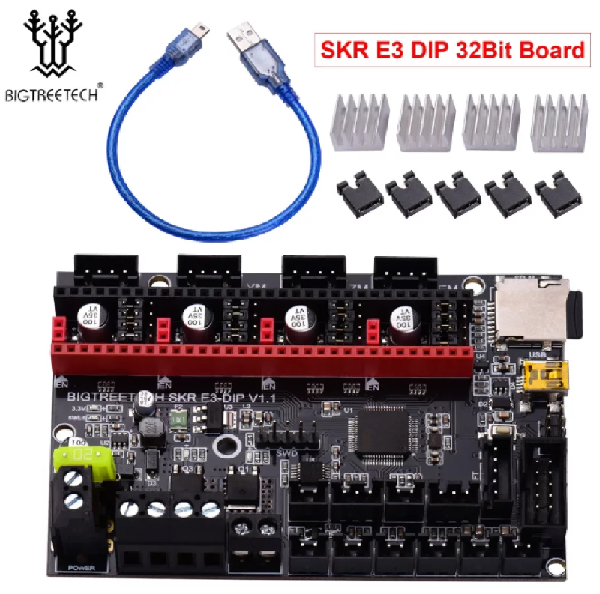
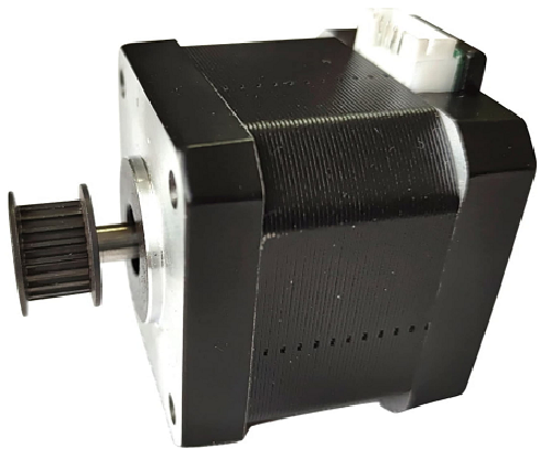
3 - Making progress!
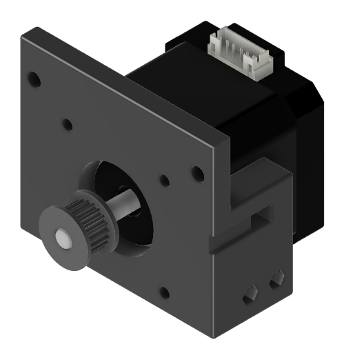
I decided to make it a real project, so I put 100% of myself into it. This was followed by a CAD phase during which I drew the support parts for the motors and the motherboard in 3D, then I was able to print them using one of my 3D printers.
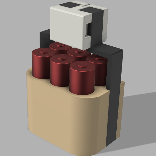
I also made the weights, which are made up of 6 empty batteries each, a weight for each end of the belt and a final weight for the pen.
Here’s the final result:
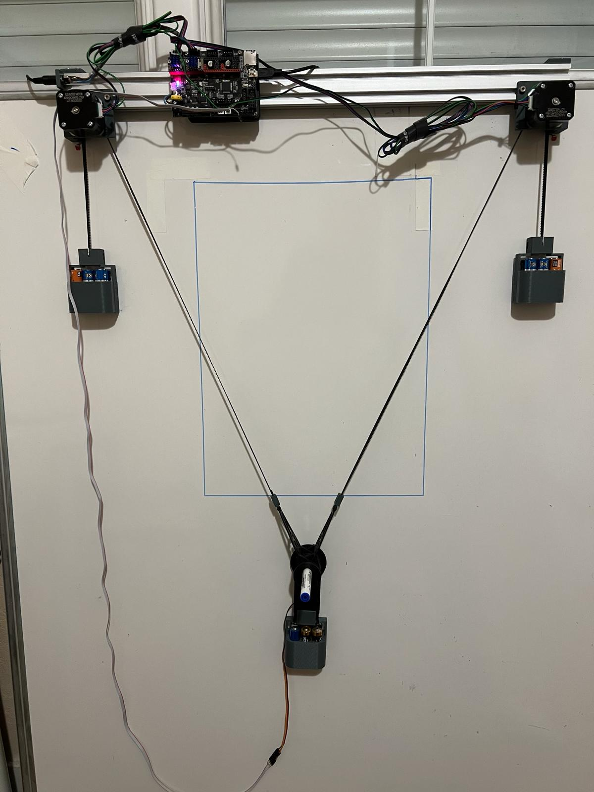
If you’re interested, the electronic schematic will be available soon.
The 3D models of the supports are already available on my github in the CreativePolargraph repository.
4 - The difficulties
Once the hardware was finished, we had to tackle the software. Using a 3D printer board, I had to adapt software called Marlin (the original is Marlin from MarginallyClever). Marlin is an open source firmware for controlling a 3D printer. MarginallyClever’s Marlin was already designed to handle polar coordinates, so I made a fork of it to adapt it to my needs. The modified Marlin is available on my github.
Once the Marlin had been adapted and recompiled for the electronic board, I had to start tuning it. It was long and tedious as every time we changed a setting, we had to reflash the firmware. The aim of the adjustments was to get a perfect rectangle in the end, to get the best possible horizontality and verticality for the most accurate drawings possible. To achieve this, I had to use mathematical formulae to calculate the Y and X positions of the pen. At first I tried to be precise on A4, then I enlarged the belts and moved the motors out of the way and switched to A3 for fun. Here’s what I came up with after several days of tweaking:
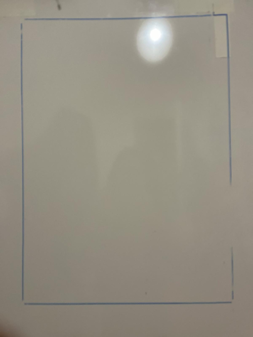
Now I can try printing a real design!
5 - The result
For Marlin to understand my design, it has to be transformed into a format called gcode (a standard format for 3D printing). To do this I use the open source software Makelangelo. I then have 2 options: either I import an svg, or I import an image file (.png, .jpg, …) and I can then apply various effects such as printing the design in small circles. Here’s an example with an image of an eye:

Here is the first drawing printed after setting the parameters:
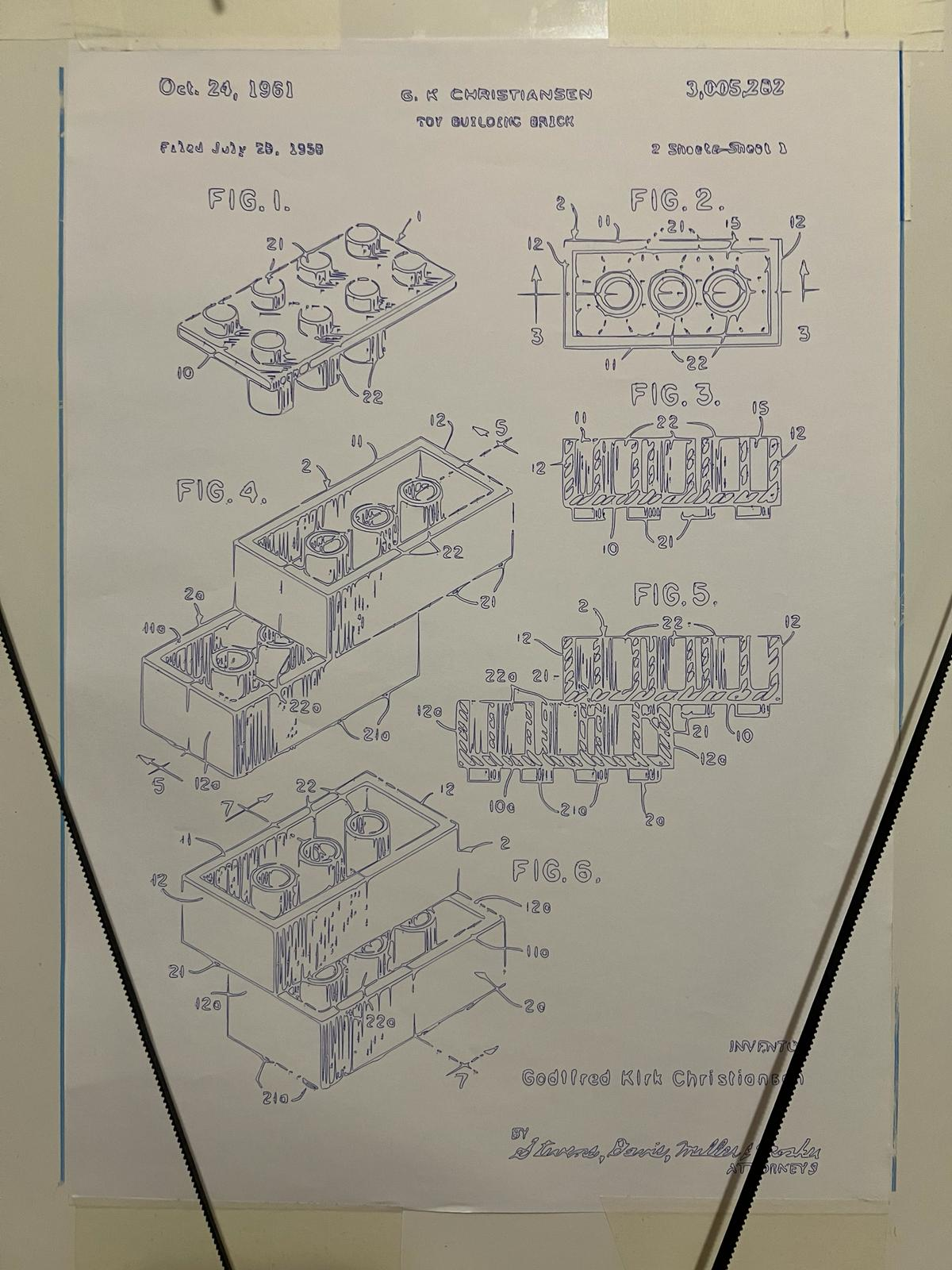
and here are some different prints:
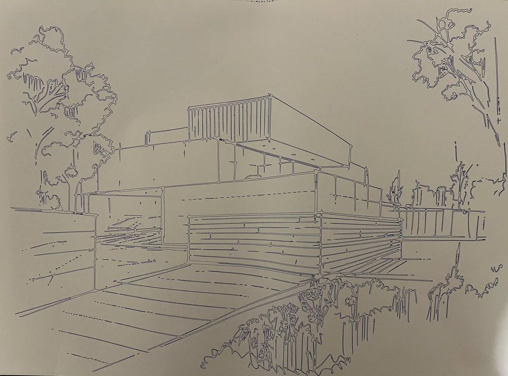
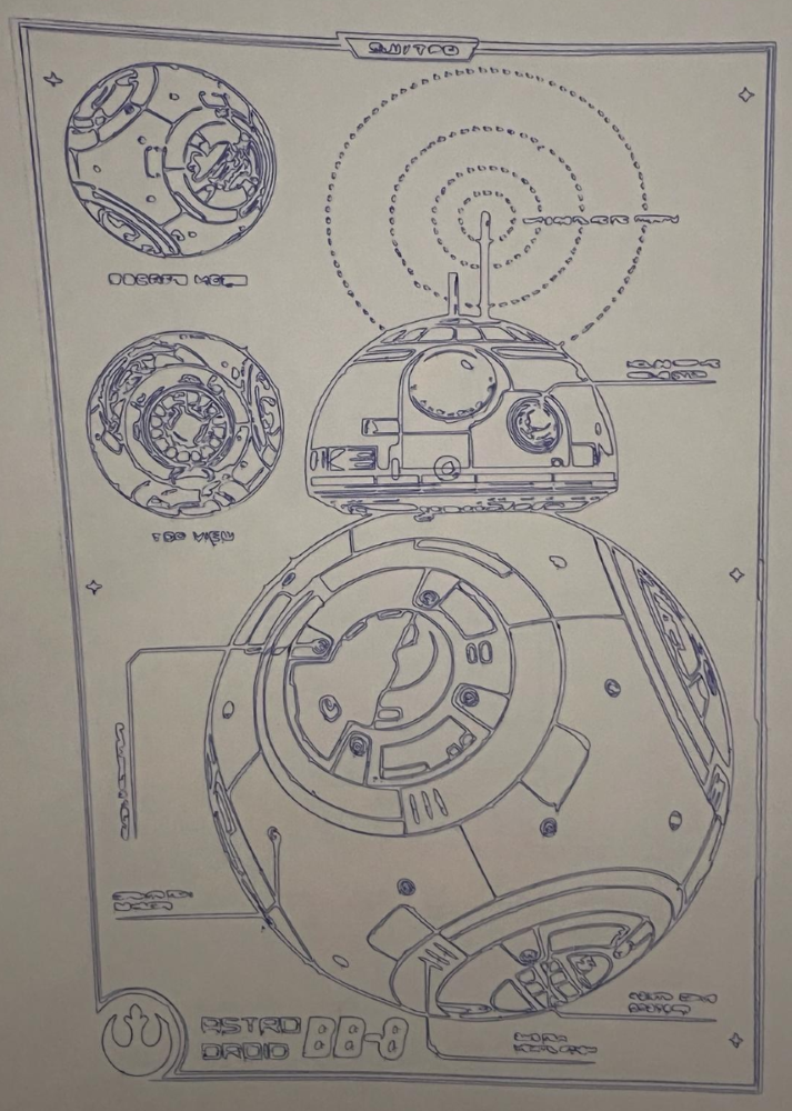
6 - Future improvements
First of all, I would like to make CreativePolargraph autonomous. To do this, I need to install a screen. At the moment, the CreativePolargraph has to remain connected to the PC to receive instructions. Unfortunately, the electronic board I use and the screen I found in the drawers are not compatible. After some research I came to the conclusion that I could make the screen work with the board, but to do that I’d have to make a link circuit between the two myself because the pins aren’t the right ones.
I also had the idea of a second version, more elaborate than the first, whose size could be unlimited (within a physical limit of belt length). At the moment I’ve got other projects I’m working on, but this second version is in the drawers. I’ll tell you all about it if it sees the light of day!
